


- 产品简介
- 产品特点
- 产品规格
- 产品尺寸
- 资料下载
- Solid shaft with key
- Solid shaft without key (C0 - C5, starting at C6 on request)
Housing Designs
- Pitch circle diameter
- Round flange
- Square flange
- Foot
Mounting Positions
- Any mounting position.
- You can find the explanation of the mounting positions and the respective quantities of lubricant in the document Quantity of lubricant for gear units ID 441871
Lubricants and Maintenance
- Mineral lubricant CLP ISO VG 220
- Option: Synthetic lubricant CLP HC ISO VG 220
Under normal operating conditions no lubricant change is required for gear unit size C0 to C5 (lubricated for life).
We recommend a change of lubricant for gear unit size C6 to C9 after approx. 10,000 hours of operation.
Motor
The asynchronous motor is designed for direct mounting.
For further information see Asynchronous Motors
Asynchronous Motor
Efficiency Classification
Europe:
According to the European ordinance (EC) 640/2009 and (EU) 4/2014, all motors with a power of 0.75 kW to 325 kW and S1 operation must comply with efficiency level IE3.
Asynchronous motors up to 0.55 kW are not affected by the European ordinance (EC) 640/2009 and (EU) 4/2014.
USA:
Since 1 June 2016, there is an absolute CC labeling obligation for motors in the USA. The motors concerned are specified in EISA 2007 + DOE Amendment 10 CFR Part 431.
- CC number CC 301B for sizes 112 to 225
- Identification on the nameplate of the motor
Identifiers and Test Symbols
- CE
- cURus
- EISA CC number including cURus from 4 kW
Motor Cooling
- Self-cooling with plastic fan wheel
- Forced ventilation (particularly recommended for frequency inverter operation at low speeds). Can be retrofitted - also on brake motors.
Motor Brake
- Spring-loaded brake
- Released electromagnetically
- The friction lining has a guide spline between brake rotor and hub and is asbestos-free.
Operating principle:
Braking is by spring force when the system is de-energised. The brake is released by an electromagnetic DC coil before the motor is powered up - or, when at rest, by a manual release device (option).
Encoder
- For vector-controlled drive controller operation use of an incremental encoder is provided for as standard.
- SSI multiturn absolute value encoder only in combination with forced ventilation.
Asynchronous Motor with Incremental Encoder
Terminal Box
Clearly designed and user-friendly terminal box for safe motor connection.
Drive Controller Recommendation
- POSIDRIVE FDS 5000 with power range 0.75 to 7.5 kW
- POSIDYN SDS 5000 with power range 0.75 to 45 kW
- SD6 with power range 0.75 kW to 45 kW
- SI6 with power range 0.75 kW to 25.9 kW
For further information see Drive Controllers.
|
Type |
Output speed [1/min] |
Ratio |
Torque on the gear unit output [Nm] |
Nominal power [kW] |
|
C002 |
20 – 1452 |
2 – 70 |
2,5 – 73 |
0.12 – 2.2 |
|
C102 |
20 – 1447 |
2 – 70 |
4,8 – 148 |
0.12 – 4 |
|
C103 |
7.5 – 17 |
82 – 184 |
66 – 148 |
0.12 – 0.25 |
|
C202 |
19 – 1180 |
2 – 70 |
24 – 249 |
0.25 – 4 |
|
C203 |
7.4 – 17 |
81 – 183 |
97 – 228 |
0.18 – 0.37 |
|
C302 |
20 – 733 |
2 – 70 |
64 – 434 |
0.55 – 7.5 |
|
C303 |
5 – 18 |
80 – 274 |
134 – 434 |
0.18 – 0.75 |
|
C402 |
21 – 749 |
2 – 70 |
94 – 671 |
0.75 – 7.5 |
|
C403 |
7.8 – 18 |
81 – 180 |
290 – 647 |
0.55 – 1.1 |
|
C502 |
21 – 754 |
2 – 70 |
65 – 991 |
0.75 – 22 |
|
C503 |
5.2 – 18 |
81 – 271 |
289 – 970 |
0.55 – 1.5 |
|
C612 |
21 – 354 |
4.2 – 69 |
221 – 1717 |
2.2 – 22 |
|
C613 |
5.3 – 30 |
49 – 266 |
272 – 1747 |
0.55 – 4 |
|
C712 |
21 – 347 |
4.3 – 70 |
337 – 2847 |
2.2 – 22 |
|
C713 |
11 – 29 |
51 – 137 |
1115 – 2668 |
2.2 – 7.5 |
|
C812 |
21 – 351 |
4.2 – 69 |
581 – 4626 |
5.5 – 30 |
|
C813 |
5.4 – 30 |
49 – 270 |
1092 – 4708 |
2.2 – 7.5 |
|
C912 |
21 – 180 |
8.3 – 70 |
1552 – 7387 |
11 – 45 |
|
C913 |
6.9 – 23 |
65 – 215 |
2601 – 8557 |
5.5 – 19 |
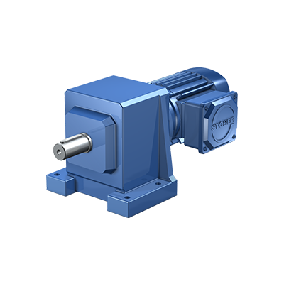
C Series

- 产品简介
- 产品特点
- 产品规格
- 产品尺寸
- 资料下载
- Solid shaft with key
- Solid shaft without key (C0 - C5, starting at C6 on request)
Housing Designs
- Pitch circle diameter
- Round flange
- Square flange
- Foot
Mounting Positions
- Any mounting position.
- You can find the explanation of the mounting positions and the respective quantities of lubricant in the document Quantity of lubricant for gear units ID 441871
Lubricants and Maintenance
- Mineral lubricant CLP ISO VG 220
- Option: Synthetic lubricant CLP HC ISO VG 220
Under normal operating conditions no lubricant change is required for gear unit size C0 to C5 (lubricated for life).
We recommend a change of lubricant for gear unit size C6 to C9 after approx. 10,000 hours of operation.
Motor
The asynchronous motor is designed for direct mounting.
For further information see Asynchronous Motors
Asynchronous Motor
Efficiency Classification
Europe:
According to the European ordinance (EC) 640/2009 and (EU) 4/2014, all motors with a power of 0.75 kW to 325 kW and S1 operation must comply with efficiency level IE3.
Asynchronous motors up to 0.55 kW are not affected by the European ordinance (EC) 640/2009 and (EU) 4/2014.
USA:
Since 1 June 2016, there is an absolute CC labeling obligation for motors in the USA. The motors concerned are specified in EISA 2007 + DOE Amendment 10 CFR Part 431.
- CC number CC 301B for sizes 112 to 225
- Identification on the nameplate of the motor
Identifiers and Test Symbols
- CE
- cURus
- EISA CC number including cURus from 4 kW
Motor Cooling
- Self-cooling with plastic fan wheel
- Forced ventilation (particularly recommended for frequency inverter operation at low speeds). Can be retrofitted - also on brake motors.
Motor Brake
- Spring-loaded brake
- Released electromagnetically
- The friction lining has a guide spline between brake rotor and hub and is asbestos-free.
Operating principle:
Braking is by spring force when the system is de-energised. The brake is released by an electromagnetic DC coil before the motor is powered up - or, when at rest, by a manual release device (option).
Encoder
- For vector-controlled drive controller operation use of an incremental encoder is provided for as standard.
- SSI multiturn absolute value encoder only in combination with forced ventilation.
Asynchronous Motor with Incremental Encoder
Terminal Box
Clearly designed and user-friendly terminal box for safe motor connection.
Drive Controller Recommendation
- POSIDRIVE FDS 5000 with power range 0.75 to 7.5 kW
- POSIDYN SDS 5000 with power range 0.75 to 45 kW
- SD6 with power range 0.75 kW to 45 kW
- SI6 with power range 0.75 kW to 25.9 kW
For further information see Drive Controllers.
|
Type |
Output speed [1/min] |
Ratio |
Torque on the gear unit output [Nm] |
Nominal power [kW] |
|
C002 |
20 – 1452 |
2 – 70 |
2,5 – 73 |
0.12 – 2.2 |
|
C102 |
20 – 1447 |
2 – 70 |
4,8 – 148 |
0.12 – 4 |
|
C103 |
7.5 – 17 |
82 – 184 |
66 – 148 |
0.12 – 0.25 |
|
C202 |
19 – 1180 |
2 – 70 |
24 – 249 |
0.25 – 4 |
|
C203 |
7.4 – 17 |
81 – 183 |
97 – 228 |
0.18 – 0.37 |
|
C302 |
20 – 733 |
2 – 70 |
64 – 434 |
0.55 – 7.5 |
|
C303 |
5 – 18 |
80 – 274 |
134 – 434 |
0.18 – 0.75 |
|
C402 |
21 – 749 |
2 – 70 |
94 – 671 |
0.75 – 7.5 |
|
C403 |
7.8 – 18 |
81 – 180 |
290 – 647 |
0.55 – 1.1 |
|
C502 |
21 – 754 |
2 – 70 |
65 – 991 |
0.75 – 22 |
|
C503 |
5.2 – 18 |
81 – 271 |
289 – 970 |
0.55 – 1.5 |
|
C612 |
21 – 354 |
4.2 – 69 |
221 – 1717 |
2.2 – 22 |
|
C613 |
5.3 – 30 |
49 – 266 |
272 – 1747 |
0.55 – 4 |
|
C712 |
21 – 347 |
4.3 – 70 |
337 – 2847 |
2.2 – 22 |
|
C713 |
11 – 29 |
51 – 137 |
1115 – 2668 |
2.2 – 7.5 |
|
C812 |
21 – 351 |
4.2 – 69 |
581 – 4626 |
5.5 – 30 |
|
C813 |
5.4 – 30 |
49 – 270 |
1092 – 4708 |
2.2 – 7.5 |
|
C912 |
21 – 180 |
8.3 – 70 |
1552 – 7387 |
11 – 45 |
|
C913 |
6.9 – 23 |
65 – 215 |
2601 – 8557 |
5.5 – 19 |